
This website is designed to help you find the best prices for products in Jordan. It's a specialized platform that lets you easily search for product prices in the market. Just type the name or number of the product you're looking for in the search box above, hit the search button, and we'll display the results sorted by the best price.


ATTINY13A-PU DIP-8 | Micro-Controllers
- Availability:
- In Stock
- Product Code:
- Brand:
- Off-Brand
You save JOD 2.55
Description:
ATTINY13A-PU DIP-8
The Atmel picoPower 8-bit AVR RISC-based microcontroller featuring 1KB of ISP Flash, 64-byte EEPROM, 64-byte SRAM, 32-Byte register file, and 4-channel 10-bit A/D converter. The device achieves up to 20 MIPS throughput at 20 MHz at 1.8-5.5 V operation.
By executing powerful instructions in a single clock cycle, the ATtiny13A achieves throughputs approaching 1 MIPS per MHz allowing you to optimize power consumption versus processing speed.

Key Parameters
Flash (kBytes):
1 kBytes
Pin Count:
8
Max. Operating Freq. (MHz):
20 MHz
CPU:
8-bit AVR
Hardware QTouch Acquisition:
No
Max I/O Pins:
6
Ext Interrupts:
6
USB Speed:
No
USB Interface:
No
Graphic LCD:
No

شرح :
0. Turn the Arduino into a AVRISP
(AVR is a family of microcontrollers. ISP means In System Programmer)
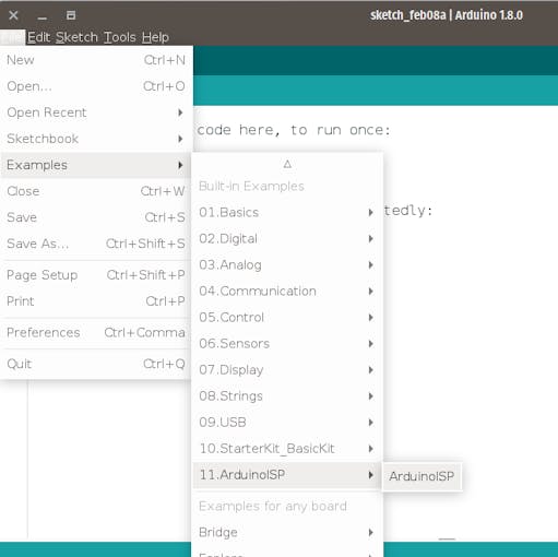
Open Arduino IDE -> File -> Examples -> 11.ArduinoISP ->ArduinoISP and upload to Arduino
1. Install hardware package for ATtiny13
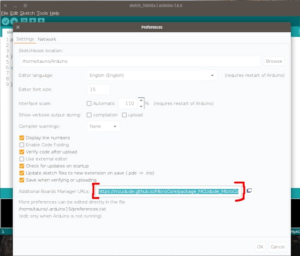
1.1 Open Arduino IDE -> File -> Preferences go to Additional Boards Manager URLsand copy this:
https://mcudude.github.io/MicroCore/package_MCUdude_MicroCore_index.jsonOk.
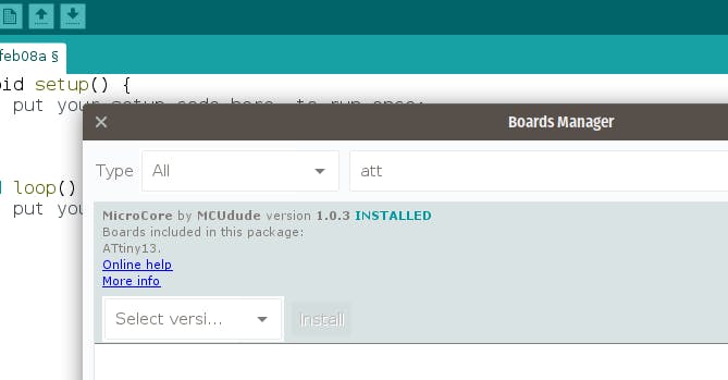
1.2 Open Arduino IDE -> Tools -> Board -> Boards manager. Find MicroCore and click Install.
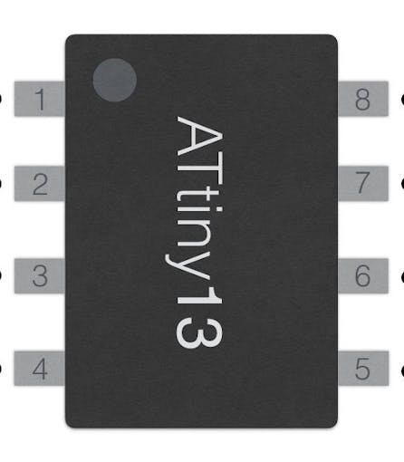
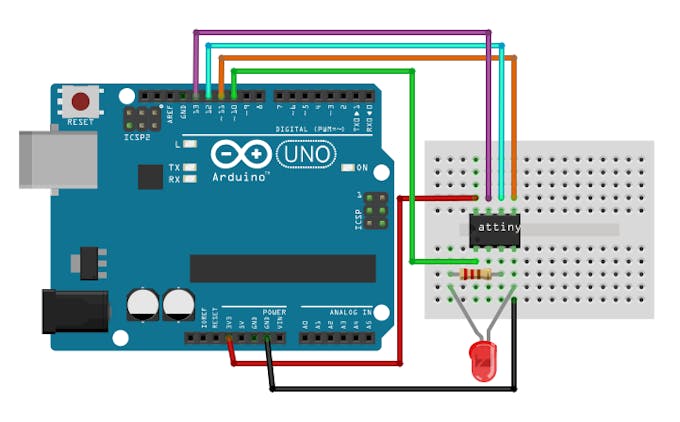
2. Connect the hardware
- ATtiny13A leg 1 -> Arduino 10
- ATtiny13A leg 5 -> Arduino 11
- ATtiny13A leg 6 -> Arduino 12
- ATtiny13A leg 7 -> Arduino 13
- ATtiny13A leg 8 -> 5v
- ATtiny13A leg 4 -> Ground (GND)
LED and resistor is needed only for testing to see does uploaded example code works or not.
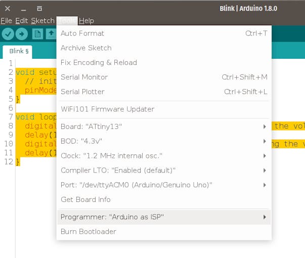
3. Arduino IDE settings
Go to Arduino IDE -> Tools and select:
- Board: ATtiny 13
- BOD: 4.3v
- Clock: 1.2 MHz internal osc.
- Compiler LTO: Enable
- Port: (Your Arduino port)
- Programmer: Arduino as ISP
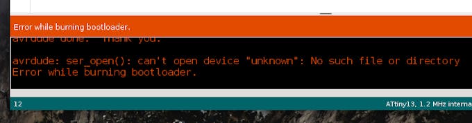
4. Burn Bootloader
(You only need to do this once per chip)
Go to Arduino IDE -> Tools -> Burn Bootloader
You might see an error, but ignore it.
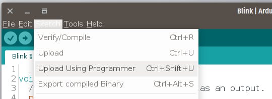
5. Upload sketch
Copy Blink sketch:
void setup() { // initialize pin 4 (ATtiny leg 3) as an output. pinMode(4, OUTPUT);}void loop() { digitalWrite(4, HIGH); // turn the LED on (HIGH is the voltage level) delay(1000); // wait for a second digitalWrite(4, LOW); // turn the LED off by making the voltage LOW delay(1000); // wait for a second} Go to: Arduino IDE -> Sketch -> Upload Using Programmer
Note:
use 1.2mhz clock
Documents:
project